


Assess operating permissives for crushers, screens, conveyors and feeders alongside normal stop and fault scenarios.
A single start command can bring several pieces of equipment into operation at a crushing and screening plant. Which motor starts when depends on material movement through the line and equipment readiness conditions. Developing a crushing plant operating sequence requires defining how motors affect each other as well as listing them.
The operating sequence follows plant flow
Start with material flow between the feed hopper, feeders, crushers, screens and conveyors. A plant may have product conveyors, recirculation lines or different operating routes. Defining a single sequence for the whole plant is insufficient without explaining which equipment is used on each route.
Readiness of downstream equipment is one of the operating conditions for the unit feeding it. Crusher auxiliary systems and manufacturer-defined ready signals are also assessed. The start sequence is developed alongside these conditions; it consists of more than time delays.
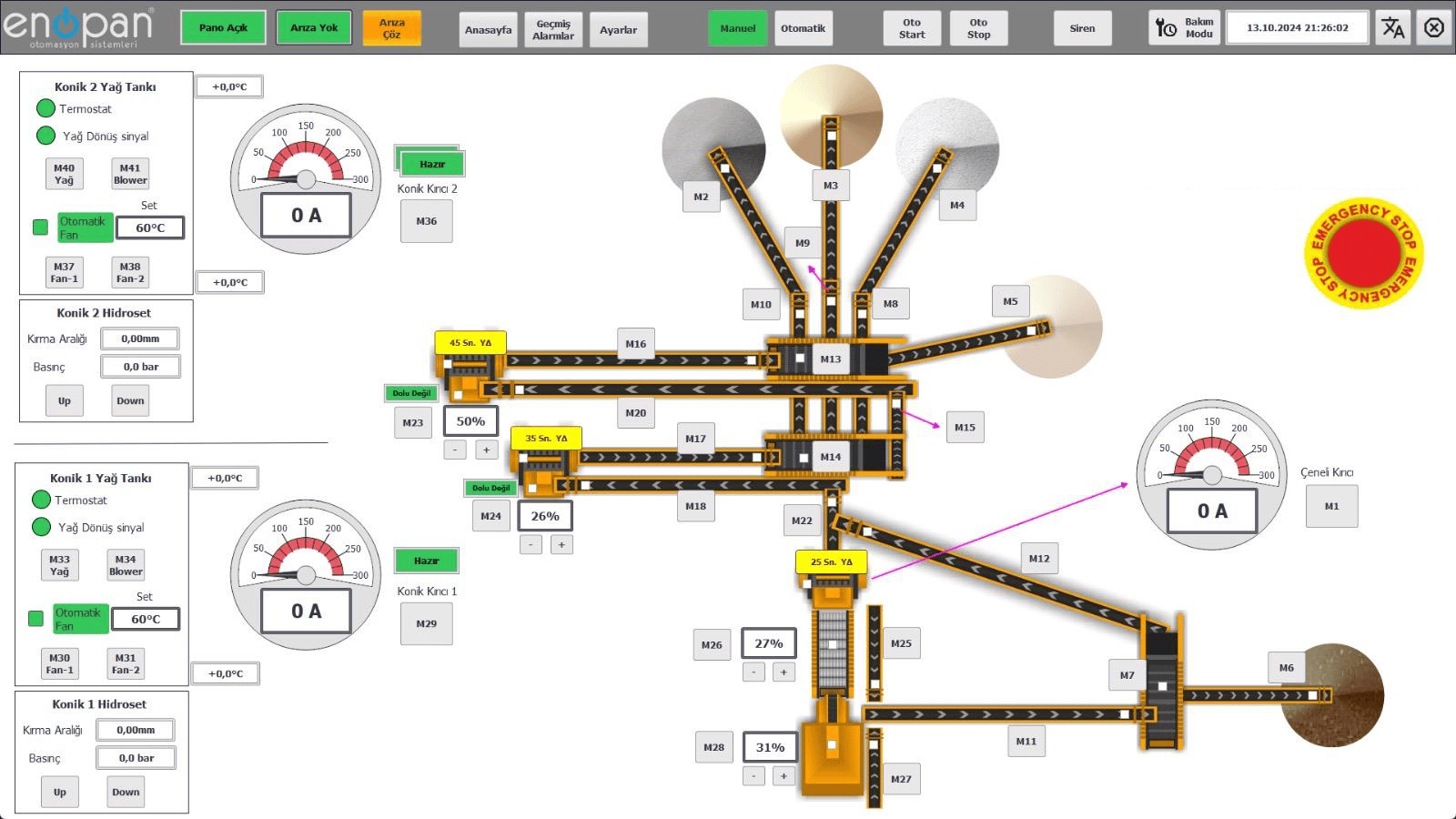
A command and actual equipment operation are different signals
The operator issuing a start command, the PLC requesting motor operation and the field returning a running signal are different stages. Distinguishing them on screen helps identify where the sequence is waiting. Available feedback depends on the existing contactor, drive and field equipment.
For example, if the next step requires a conveyor running signal, that condition should be stated explicitly in the control sequence. The description shown if the expected signal does not arrive should name the relevant equipment. The operator can then see the missing condition rather than a general “line not ready” message.
Material in the line matters during a normal stop
A planned production stop differs from cutting power to every motor at once. Stopping feed and conveying material remaining in the line are considered in the normal stop sequence. Timing and stop conditions are determined according to plant configuration and equipment manufacturers’ requirements.
The same plant may also need partial stops. Which units can continue running when a product conveyor is taken out of service is assessed alongside the availability of an alternative material route. This decision must be consistent with line selection on the operator screen.
Fault relationships should be defined for each piece of equipment
When equipment fails, units feeding it may need to stop. The equipment affected is defined according to material flow and fault type. Each relationship is examined rather than assuming every alarm stops the entire plant in the same way.
Normal stopping, process faults and emergency stopping are separate functions. Process sequencing is designed alongside equipment protection and safety requirements. Restart conditions after fault clearance are also included; an alarm disappearing is not itself a restart command.
What changes when a new conveyor or crusher is added?
Adding a unit to a line involves more than adding a motor symbol to the screen. PLC inputs and outputs, operating permissives, panel connections, selected material routes and stop relationships may all change. The initial assessment determines whether existing capacity can accommodate the addition.
| Change | Points to review together |
|---|---|
| New conveyor | Upstream and downstream units, running feedback and fault relationships |
| New crusher or screen | Auxiliary systems, ready signals, feed and discharge connections |
| Alternative product route | Route selection, equipment to use and operator screen |
How is the control sequence verified on site?
During commissioning, the prepared sequence is compared against equipment commands and field feedback. Manual and automatic operation, normal stops, defined fault conditions and restart conditions are examined through planned tests. The equipment and expected behaviour covered by each test are documented in advance.
At Enopan, we address PLC software, HMI/SCADA screens and control panels for mobile, stationary and tracked crushing and screening plants through these equipment relationships. Sharing the current line flow, sequence changes required and any panel photographs and PLC/HMI details starts the initial assessment.
Review your line’s operating sequence with us
Share the equipment list and material routes. We can define the software and panel scope for a new installation, additional unit or changes to an existing sequence.