

Assess temperature points, airflow and feed/discharge relationships together according to the dryer design.
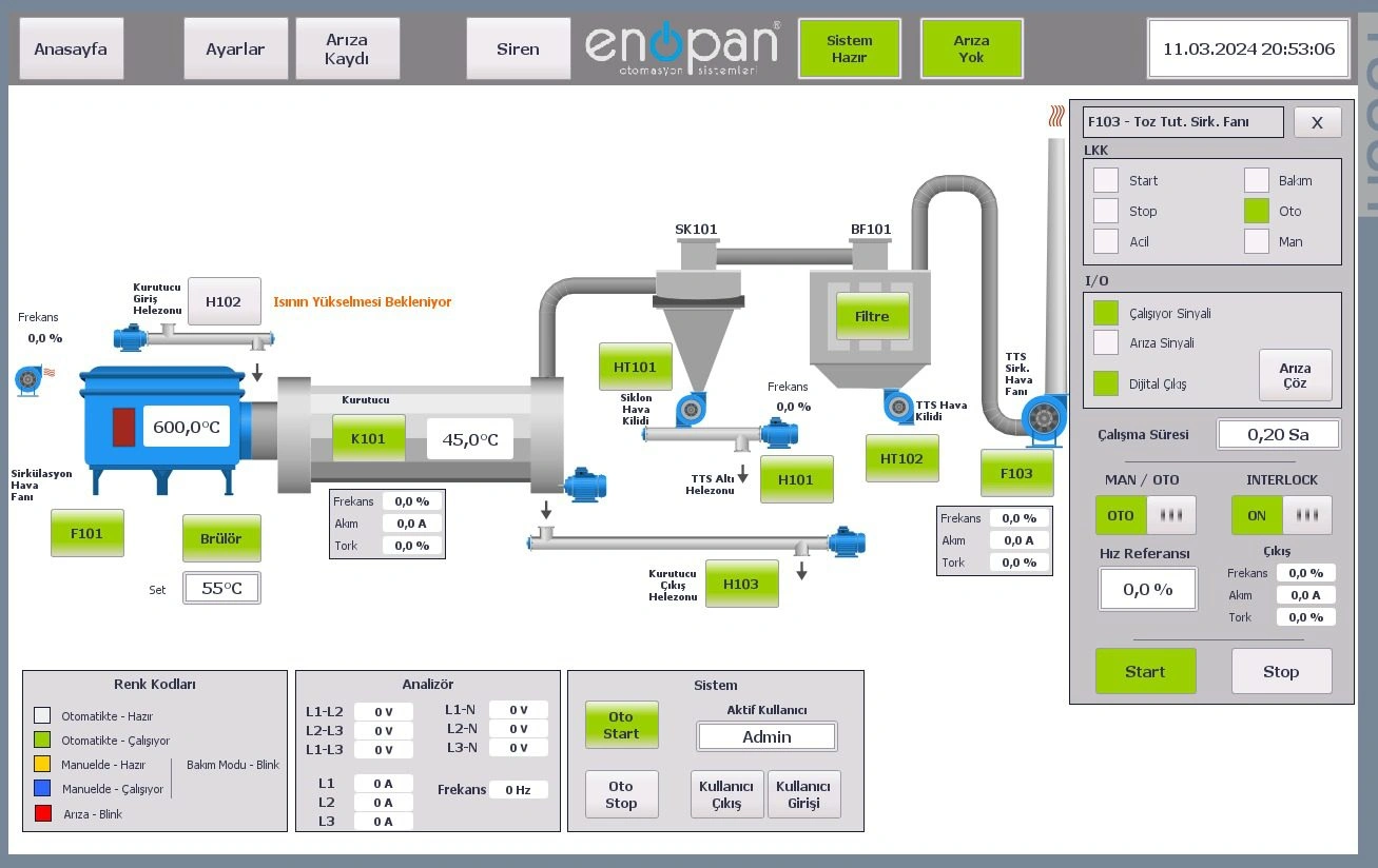
Displaying temperature on an industrial dryer screen does not describe the full drying control process. Heating, fans, material feeding, conveying and discharge equipment work together. The automation scope depends on the material, dryer design, existing measurements and equipment manufacturer’s operating requirements.
Define the role of temperature measurement points
Temperatures measured at different dryer points may represent different conditions. Specify where an inlet, outlet or other process measurement is taken and which decision uses it. A value labelled only “dryer temperature” may not be clear enough for operators.
Sensor type, measuring range and transfer to the control system are examined using the existing equipment. System behaviour when measurement is unavailable or invalid is also defined. Operating temperature settings and alarm limits have separate roles that are explained individually.
Fans and airflow are addressed in the same sequence
Fans perform airflow-related functions in a drying system. An automation command to run a fan and verification of the required airflow are different signals. Available feedback and measurements are defined according to existing plant hardware.
The project describes how other units respond when a fan or connected equipment is not ready. Where fan speed control exists, the conditions or settings it depends on are also examined. Operating relationships are developed to suit dryer, heater and fan manufacturer requirements.
Why are material feeding and discharge examined together?
The quantity and movement of material entering a dryer affect process operating conditions. The roles of feeders, drums, conveyors and discharge equipment are shown in the flow diagram. Define when each unit is considered ready and when it transfers material downstream.
If a sawdust dryer connects to a pellet line, its operating relationship with downstream conveying and press units is also addressed. For a standalone dryer, upstream feed and downstream discharge equipment are assessed within their own scopes. The same control sequence is not expected to suit all dryers.
How are time and temperature settings defined?
Time- and temperature-based settings are developed according to dryer design and process requirements. Operator-adjustable fields, units and permitted ranges are clearly defined. The operating conditions under which changes take effect are also part of screen design.
Different materials are not assumed to use the same temperature or time. Process information requiring assessment when changing materials should be shared at the outset. Control software is based on measurements actually available at the plant and defined equipment functions.
Normal stops and alarm conditions are separated
A planned production stop, process fault and emergency stop are different functions. Behaviour of heating, airflow and material handling equipment in each case is designed around dryer requirements. A general sequence is not based on stopping every motor simultaneously with one command.
The measurement or equipment associated with an alarm should be clear to the operator. Restart conditions are defined according to the fault and process state. Protection and safety functions are assessed against technical requirements separate from the normal controls on the process screen.
What information is needed for existing dryer automation?
Share the material, dryer type, heating arrangement and fan, feed and discharge equipment. Existing temperature points, PLC/HMI details, electrical drawings and panel photographs support the review. If there is a problem, state the operating step and measurement present when it occurs.
At Enopan, we address temperature, time and equipment operating sequences together in industrial drying systems. For standalone dryers or integrated production lines, we define software, operator screen, panel and on-site commissioning scope from the existing plant. Data to monitor and records required are also discussed within this scope.
Share your dryer equipment and measurement details
Assess the control scope with us using the material, dryer type and change required. We can address temperature points, fans and material transfer within the same operating sequence.